
Highly Conductive PP (Polypropylene) for Bipolar Plate Development: What Data Matters?
Highly conductive PP plate development requires more than a low resistance value on a standard test plaque.
For bipolar plates and contact parts, through-thickness behavior, flatness, compression, contact resistance and molding stability can decide success or failure.
This page explains which data matter when moving from conductive PP pellets to a molded plate used in an electrical assembly.
DEYU supports material selection with sample validation, geometry review and comparison against the customer’s real performance criteria.
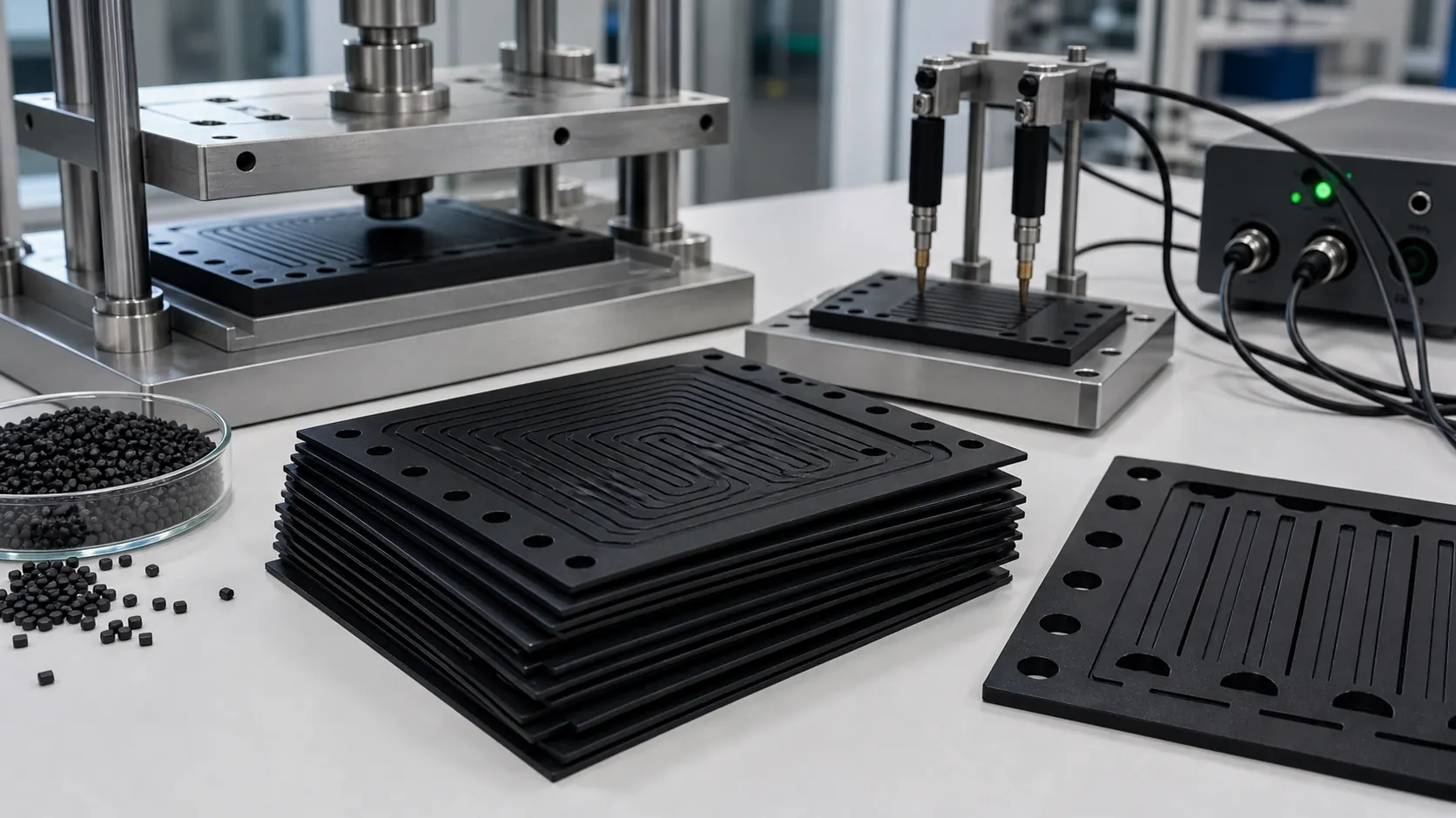
Buyer and engineer FAQ
Questions engineers often ask about this material route
Where can PP with a conductive plastic requirement be used?
Typical fields include ESD trays, electronic housings, fixtures, EMI parts and antistatic logistics parts. For this article, DEYU would first confirm the working environment, wall thickness, expected lifetime and whether Conductive Plastics, DGK-PP DD2-3A Conductive PP matches the part geometry or needs formulation adjustment.
What are the main performance indicators for the "conductive plastic" target on PP?
Focus on surface resistance, volume resistance, dispersion uniformity, impact strength and molding stability. Buyers should ask for data on molded parts, not only pellet data, because gate position, filler orientation and thickness can change the final value.
What should engineers watch during injection molding or processing?
For PP, a practical starting window is 190-230°C melt / 30-60°C mold. Avoid excessive filler loading, control weld lines and verify resistance on the molded part. Final parameters should follow part thickness, gate design and the actual machine.
What details help DEYU recommend Conductive Plastics, DGK-PP DD2-3A Conductive PP more accurately?
Send the current resin or grade, drawing or photo, wall thickness, annual quantity, target standard, failure mode and required color. If a reference grade already passed one test but failed in production, include both data sets.
For a precise recommendation, share the part drawing, base resin, target performance, processing method and test standard with DEYU.
This page is for engineers and buyers who need to select conductive plastics by part function, resistance range and molded-part validation.
Conductive Plastics and DGK-PP DD2-3A Conductive PP. For low-resistance PP directions, start with the conductive plastics platform and then confirm whether DD2-3A level resistance fits the part function.
1. Background / Problem
High-conductive PP plate development is different from ordinary ESD tray or housing selection. The part may need low resistance, through-thickness conductive behavior, contact stability under compression and flat molded geometry.
A material that passes a surface resistance plaque test may still fail if plate flatness, thickness uniformity or contact resistance is unstable.
2. Technical Difficulty / Why It Happens
Conductive fillers must be dispersed enough to create a continuous conductive network without destroying PP molding flow and plate surface quality.
For plate applications, the most important data can include surface resistance, volume-related behavior, compression contact resistance, channel replication, flatness, thickness variation and mechanical durability.
3. DEYU Material Direction
DEYU conductive plastics cover PP and other base resins using carbon black, carbon fiber, graphite, carbon nanotube or compound conductive systems. For low-resistance PP projects, DGK-PP DD2-3A provides a conductive 10^2-10^3 ohm direction for extrusion and injection molding.
Bipolar plate development or similar conductive plate projects still require part-level validation because conductivity, contact pressure and geometry are coupled.
4. Reference Product Data
| Direction | Corrected data focus |
|---|---|
| Conductive plastics platform | PP / PE / ABS / PA / POM and application-specific engineering plastics with adjustable electrical behavior |
| DGK-PP DD2-3A | Conductive 10^2-10^3 ohm; extrusion and injection molding |
| Plate development checks | Surface resistance, volume-related behavior, contact resistance under compression, flatness and thickness uniformity |
| Data limitation | Final electrical and mechanical targets must be confirmed on the actual plate geometry |
5. Real Customer Application Case
A customer developed a thin conductive PP plate. The plaque resistance was acceptable, but molded plates showed uneven contact behavior after compression and thickness variation near flow-end regions.
6. Validation Data Table
| Item | Standard conductive PP plaque | Previous plate trial | DEYU conductive PP validation direction |
|---|---|---|---|
| Sample type | Flat plaque | Molded plate | Molded plate + compression check |
| Resistance direction | Met target on plaque | Varied by plate zone | Target mapped by zone |
| Compression contact stability | Not checked | Medium | Target improved |
| Flatness out-of-limit rate | Not applicable | 8.0% | Target <4.0% |
| Thickness variation issue | Not applicable | Medium | Target reduced by process tuning |
| Channel replication | Not checked | Partial | Target confirmed on real mold |
| Tasa interna de aprobación | 85% | 74% | Target >88% after validation |
This case is based on a real customer scenario from DEYU's internal project records.
7. Result Interpretation
For high-conductive PP plates, one resistance number is not enough. The buyer should define whether the function depends on surface dissipation, through-thickness conduction or contact under compression.
The material direction should be selected only after combining electrical testing with plate molding and compression validation.
8. Suitable Applications
- High-conductive PP plates
- Bipolar plate development samples
- Conductive molded plates
- Low-resistance PP components
- Conductive structural sheets requiring compression contact checks
9. What Buyers Should Provide
Buyers should provide target resistance or conductivity, plate thickness, required test method, contact pressure, geometría de canal, flatness tolerance, molding method, current failure mode and trial quantity.
Заключение
Final material selection should be confirmed on the actual part: resistance, mechanics, processing, geometry and service conditions need to be evaluated together.
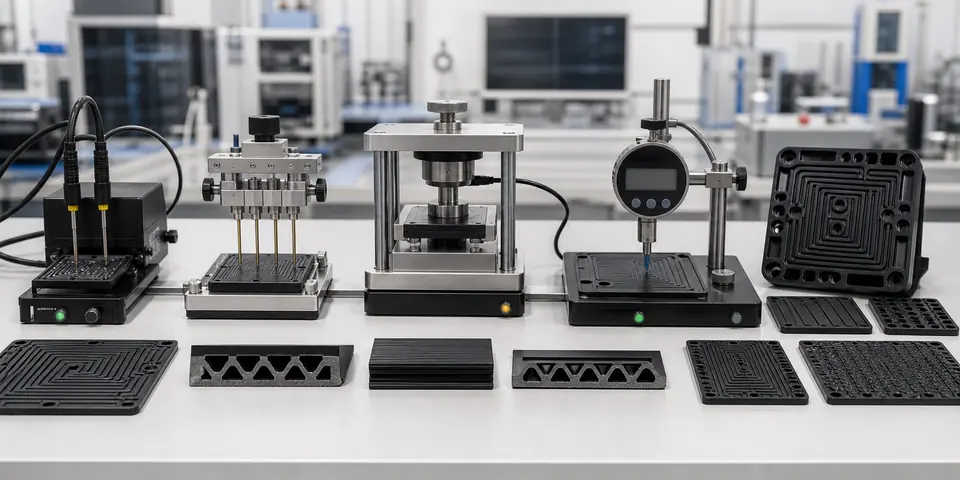
Expanded Development Notes for High-Conductive PP Bipolar Plate Compounds
High-conductive PP for bipolar plate development is more difficult than ordinary conductive PP because the compound must satisfy several targets at the same time. A low resistance value is not enough. The molded plate also needs stable flow into thin ribs, acceptable flatness, enough mechanical integrity for sealing pressure, and resistance stability after heat, humidity or chemical exposure. If one target is optimized alone, another target often becomes unstable.
DEYU therefore treats bipolar-plate PP as a formulation and processing window, not as a single catalogue grade. Graphite, conductive carbon black, carbon fiber or CNT can all contribute to the conductive network, but each filler changes melt viscosity, shrinkage, brittleness and surface condition. The development question is not only “how low can the resistance go,” but “can the part be molded repeatedly while keeping resistance, flatness and sealing behavior inside the same window.”
Why Bipolar Plates Are Harder Than Normal Conductive PP
Many conductive PP parts are thick enough that flow length and flatness are manageable. Bipolar plates are different. Channels, ribs, sealing lands and thin walls create a long flow path and many areas where filler orientation can change. A formulation that shows good resistance on a flat plaque may become uneven across a molded plate. Local high resistance can appear near weld lines, thin ends or surfaces with poor filler contact.
Mechanical behavior is equally important. A plate that is too brittle can crack during assembly or stack compression. A plate that creeps too much can lose sealing pressure. A plate that warps can create uneven contact pressure, which then affects both electrical contact and leakage risk. For this reason, DEYU links electrical data with molded-part geometry and compression testing rather than approving a compound from plaque resistance alone.
| Development variable | Risk if ignored | DEYU validation focus |
|---|---|---|
| Surface and volume resistance target | A plaque value may not represent the whole molded plate. | Map multiple positions, including weld lines, thin ends and sealing areas. |
| Filler loading and dispersion | Too much filler raises viscosity and brittleness; poor dispersion causes hot spots. | Check melt flow, microscopy or surface uniformity and lot-to-lot stability. |
| Flow length and channel detail | Thin ribs may short-shot or show uneven filler packing. | Mold representative channel geometry before committing to the final tool. |
| Plate flatness | Warp affects sealing pressure and contact resistance. | Measure flatness after molding, after conditioning and after thermal cycling. |
| Compression and sealing pressure | Creep can reduce contact and cause leakage risk. | Run compression set or fixture loading under the expected temperature range. |
| Chemical and thermal aging | Conductive network or PP matrix may drift in service. | Compare resistance and mechanical data before and after exposure. |
Conductive Filler Packing and Process Stability
The conductive network in high-conductive PP is built by filler contact. Graphite can support conductivity and dimensional stability, conductive carbon black can improve network continuity, and carbon fiber or CNT may reduce the percolation threshold. However, these fillers compete for space inside a PP matrix. Higher packing can lower resistance but reduce flow, increase tool wear and make edge cracking more likely. The final choice depends on the plate thickness, channel depth, molding machine, target resistance and downstream assembly pressure.
A useful pilot route starts with laboratory compounding, plaque resistance, melt-flow check and impact or flexural screening. The next step is a thin plate or channel sample, not a large commercial mold. Resistance should be mapped across the part; flatness should be measured after cooling; and the plate should be compressed under a fixture that represents the sealing load. If those results are stable, the formulation can move to a larger batch window and stricter lot-control plan.
When Custom Formulation Is Necessary
Generic conductive PP may be enough for trays, housings or grounding parts, but bipolar plate development often requires a custom route. The target may include a special resistance range, low warpage, specific flow length, improved toughness, chemical exposure or a cost ceiling. DEYU adjusts filler package, PP base resin, compatibilization and processing recommendations together, because changing only one item rarely solves the complete plate problem.
The most useful inquiry includes desired surface or volume resistance, plate size, channel thickness, molding method, sealing pressure, service temperature, chemical environment, target lifetime and whether the plate is for prototype evaluation or scaled production. With these details, DEYU can recommend whether the project should start from conductive PP, a higher graphite-loading route, a hybrid filler system or a different polymer base.