
Carbon-Fiber Conductive PA66 for High-Strength Structural Components
Carbon-fiber conductive PA66 is used when a part needs conductivity together with stiffness, heat resistance and structural load capacity.
The material route must balance conductive pathways, fiber orientation, warpage, moisture conditioning and impact sensitivity after molding.
This page explains why a simple resistance target is not enough for brackets, fixtures, housings or load-bearing electrical components.
DEYU supports grade selection, sample molding and validation against the real part geometry and operating environment.
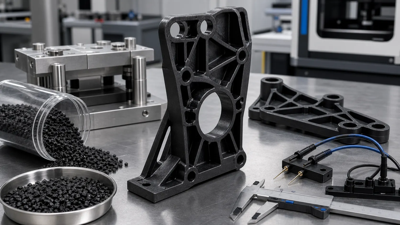
Buyer and engineer FAQ
Questions engineers often ask about this material route
Where can PA66 with a conductive plastic requirement be used?
Typical fields include ESD trays, electronic housings, fixtures, EMI parts and antistatic logistics parts. For this article, DEYU would first confirm the working environment, wall thickness, expected lifetime and whether DGK-PA66 CF15L-CF40L Custom Carbon Fiber PA66, Reinforced Plastics matches the part geometry or needs formulation adjustment.
What are the main performance indicators for the "conductive plastic" target on PA66?
Focus on surface resistance, volume resistance, dispersion uniformity, impact strength and molding stability. Buyers should ask for data on molded parts, not only pellet data, because gate position, filler orientation and thickness can change the final value.
What should engineers watch during injection molding or processing?
For PA66, a practical starting window is 260-295°C melt / 75-100°C mold, dry before molding. Avoid excessive filler loading, control weld lines and verify resistance on the molded part. Final parameters should follow part thickness, gate design and the actual machine.
What details help DEYU recommend DGK-PA66 CF15L-CF40L Custom Carbon Fiber PA66, Reinforced Plastics more accurately?
Send the current resin or grade, drawing or photo, wall thickness, annual quantity, target standard, failure mode and required color. If a reference grade already passed one test but failed in production, include both data sets.
For a precise recommendation, share the part drawing, base resin, target performance, processing method and test standard with DEYU.
This page is for engineers and buyers who need to select conductive plastics by part function, resistance range and molded-part validation.
DGK-PA66 CF15L-CF40L Custom Carbon Fiber PA66 and Reinforced Plastics. Use this route when conductivity must work together with high stiffness, dimensional stability and PA66 heat resistance.
1. Background / Problem
Some conductive parts cannot use PP, PE or ABS because the application requires higher rigidity, heat resistance and structural load capacity. In these cases, carbon-fiber reinforced PA66 is often considered.
PA66 is sensitive to moisture, drying, conditioning and dimensional change. When carbon fiber is added for conductivity and reinforcement, fiber orientation, warpage and notch sensitivity become part of the material selection problem.
2. Technical Difficulty / Why It Happens
Carbon-fiber conductive PA66 must form a conductive pathway while keeping high flexural stiffness, controlled shrinkage, acceptable impact behavior and stable dimensions after conditioning.
If a part passes resistance testing but fails assembly, flatness or tolerance, the carbon fiber content and molding process still need adjustment.
3. DEYU Material Direction
DEYU may recommend DGK-PA66 CF15L-CF40L for high-strength conductive structural components. Existing product data positions this direction as customizable 15%-40% carbon fiber reinforced PA66 with high strength, high stiffness and conductive performance.
Lower carbon fiber content may be used when toughness and moldability are more important. Higher carbon fiber content may be considered when rigidity, dimensional stability and conductivity are more important, but warpage and cracking risk must be monitored.
4. Reference Product Data
| Property | DGK-PA66 CF15L-CF40L Direction |
|---|---|
| Base resin | PA66 |
| Reinforcement route | Carbon fiber reinforced PA66 |
| Carbon fiber content | 15%-40% customizable |
| Performance direction | High strength, high stiffness and conductive performance |
| Processing | Injection molding; drying required |
| Typical applications | Mechanical parts, electronic and electrical equipment, high-strength conductive structural components |
5. Real Customer Application Case
A customer needed a conductive structural support near electrical equipment. The original conductive ABS had acceptable resistance but insufficient stiffness. A high-carbon-fiber PA66 trial improved rigidity but caused warpage and assembly cracking.
Technical route, application scenarios and real-project validation
For this topic, the useful work starts beyond the generic material name. Engineering validation begins with the failed part, the property that must be held and the test method that will confirm the result after processing.
How DEYU narrows the route
Projects like this follow a carbon-fiber reinforced route balancing stiffness, warpage and processability. The team first defines the target indicator and the limits for color, impact strength, flow, shrinkage and surface quality. The goal is not to choose one “best” additive, but to define a repeatable formulation window on the molded part.
Where this logic is applied
- lightweight rigid brackets and housings
- metal-replacement structural parts
- components requiring modulus, dimensional stability and moldability at the same time
These scenarios differ in wall thickness, cycle time, appearance requirements and inspection method. The same material family can need a different adjustment when the mold, part geometry or test method changes.
Anonymized customer case and validation method
In one real anonymized customer project, the starting route was already directionally correct, but the part-level validation was not stable enough. DEYU kept the original application goal and changed the validation parameters and formulation balance rather than narrowing the use case artificially.
| What was compared | Why the previous route was weak | What was adjusted | How the result was evaluated |
|---|---|---|---|
| Material before replacement | the previous grade could not reach the stiffness target or warped after molding, especially with long flow length and thin walls | carbon-fiber loading, retained fiber length, flow direction, shrinkage, mold temperature and gate location | DEYU tuned both fiber content and moldability; the trial batch was checked for stiffness, flatness and surface quality |
| DEYU route | The value on a standard specimen did not fully represent the real molded part. | Short sample run, control specimens, processing window and measurement method. | The result was recorded as a working range; serial supply still needs confirmation on the actual mold. |
This makes the article useful for both engineers and purchasers: the engineer can see what must be tested, while purchasing can see what information should be sent before requesting samples.
6. Validation Data Table
| Item | Conductive ABS | Previous PA66-CF trial | DEYU DGK-PA66 CF15L-CF40L trial direction |
|---|---|---|---|
| Trial quantity | 600 pcs | 800 pcs | 1,200 pcs |
| Resistance direction | Met basic target | Met target | Target meets project range |
| Flexural stiffness feedback | Insufficient | High | Target balanced stiffness |
| Warpage out-of-limit rate | 3.5% | 9.0% | Target <4.5% |
| Assembly cracking rate | 1.8% | 5.2% | Target <2.5% |
| Drying sensitivity | Low | High | Controlled by process window |
| Molding scrap rate | 3.0% | 6.8% | Target <4.0% |
| Tasa interna de aprobación | 79% | 76% | Target >90% after validation |
This case is based on a real customer scenario from DEYU's internal project records.
7. Result Interpretation
For conductive PA66 structural parts, the best direction is not always the highest carbon fiber content. More fiber can improve rigidity and conductive stability, but it can also increase warpage and cracking risk.
A practical solution evaluates resistance, stiffness, moisture conditioning, dimensional stability and assembly performance together.
8. Suitable Applications
- Conductive PA66 brackets
- Electrical structural supports
- High-rigidity conductive components
- Mechanical parts near electronic assemblies
- Carbon-fiber reinforced nylon parts
- Molded parts requiring both strength and ESD control
9. What Buyers Should Provide
Buyers should provide the target resistance range, stiffness or strength target, current material and failure reason, part drawing, tolerance, wall thickness, rib structure, drying and molding process, assembly method and current warpage or cracking data.
Заключение
Final material selection should be confirmed on the actual part: resistance, mechanics, processing, geometry and service conditions need to be evaluated together.
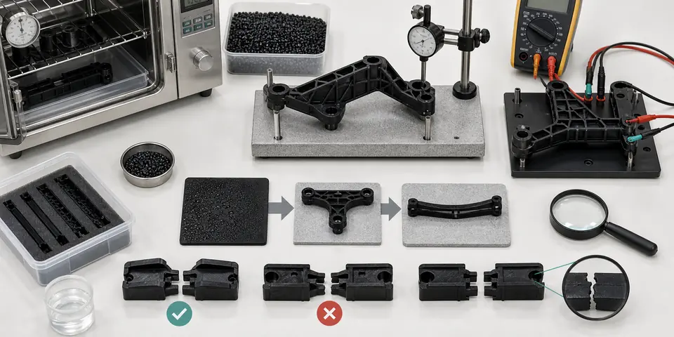
Engineering decision path
This page is intended to work as a material-selection brief, not only as a product introduction. The engineering route starts with the failure mode, then narrows the base resin, additive package, molding window, and validation method.
- Use carbon-fiber conductive PA66 when the part needs both electrical function and structural stiffness, not only a conductive surface.
- Review load direction, gate location, weld lines, and fiber orientation because strength and resistance can vary across the molded part.
- Balance conductivity with toughness, warpage, surface finish, tool wear, and moisture conditioning before approving the route.
- Validate resistance, tensile or flexural behavior, dimensional stability, and assembly fit on molded parts from the production-like tool.
Anonymous customer cases
Case 1: load-bearing bracket with ESD requirement
The customer needed stiffness and conductive behavior in one material. DEYU suggested carbon-fiber conductive PA66 trials and focused inspection on fiber orientation, weld-line strength, and resistance at the mounting areas.
Case 2: compact structural housing near electronics
The project required strength but could not accept metal weight. DEYU helped compare carbon-fiber PA66 against standard conductive compounds, with validation centered on warpage, screw bosses, and resistance stability.
How DEYU supports the project
- DEYU can adjust conductivity, wear resistance, toughness, flame-retardant direction, color, and processing flow as a combined formulation target instead of treating each property separately.
- Sample batches can be aligned with customer molds, part thickness, gate position, and expected tests before commercial supply.
- For international inquiries, DEYU engineers help translate application requirements into resin route, test items, sample plan, and risk points for purchasing and technical teams.
Expanded Engineering Notes for Conductive Carbon-Fiber PA66
Carbon-fiber conductive PA66 is often selected when a part has to combine ESD control, dimensional stability and structural load bearing in one molded component. The material route should not be judged only by a high tensile-strength number. For brackets, carrier arms, sensor housings, pump-adjacent parts and equipment fixtures, the real question is whether the finished part keeps stiffness, resistance and tolerance after molding orientation, moisture conditioning and repeated assembly load.
In DEYU projects, the first check is the service load path. A carbon-fiber network can raise modulus and reduce surface or volume resistance, but the fiber direction follows melt flow. A rib that is strong along the flow direction may be less stable across the flow direction, and a measured resistance value on one face may not represent every critical grounding surface. This is why the material discussion should include gate position, wall thickness, screw boss layout, insert area and the exact point where the customer intends to measure resistance.
When High Strength Is Not Enough
High-strength PA66 is useful only when the molded geometry lets that strength work. If the component has snap hooks, thin living hinges, sharp ribs or heavy press-fit zones, the same reinforcement that improves stiffness can reduce local toughness. A practical development route compares dry-as-molded samples, moisture-conditioned samples and parts after several thermal cycles. The comparison shows whether the failure risk is stiffness loss, clearance drift, brittle cracking or unstable electrical reading.
For metal replacement, DEYU normally asks for the original metal part, the target plastic drawing and the assembly force. The plastic grade may pass a simple tensile test yet still fail because the deflection under fixture load is too high. A better validation method is to measure deformation at the functional position, not only the strength of a standard test bar.
| Design checkpoint | Why it matters | Practical validation |
|---|---|---|
| Flow direction and gate layout | Fiber orientation changes modulus, shrinkage and local resistance. | Mold test bars and a representative part, then compare longitudinal and transverse values. |
| Moisture conditioning | PA66 absorbs moisture; stiffness, impact and dimensions change after conditioning. | Measure dry-as-molded and conditioned parts before approving the final tolerance. |
| Ribs, bosses and inserts | Stress concentration can create cracks even when the base grade looks strong. | Use a prototype with real screw bosses, inserts and rib thickness instead of a flat plaque only. |
| ESD measurement points | Texture, weld lines and skin layers can change surface resistance. | Mark repeatable points and test before cleaning, after cleaning and after handling. |
| Metal replacement target | Aluminum replacement requires deflection control, heat resistance and assembly stability. | Compare functional deflection under the same fixture load used in the finished product. |
Filler Network and Anisotropy Control
The conductive path in carbon-fiber PA66 is a connected filler network, not a uniform metal plate. A higher filler level may reduce resistance, but it can also narrow the processing window, raise melt viscosity, make weld lines more sensitive and reduce surface quality. The correct grade is therefore a balance: enough conductive network for the ESD or grounding target, enough fiber length for stiffness, and enough base-resin toughness for assembly.
DEYU treats the first trial as a mapping step. We prefer to record resistance on several molded surfaces, bending stiffness in the expected load direction, and visual condition around weld lines. If the data are uneven, the solution may be a gate change, a slightly different fiber system, a hybrid conductive package or a target-resistance adjustment. This prevents the common mistake of only increasing carbon content until processing becomes unstable.
Recommended Development Sequence
A stable project normally starts with a baseline: the current metal or plastic part, its failure mode and the required resistance range. Next, DEYU defines the minimum modulus, impact target, heat requirement, color limitation and surface-resistance range. The first molded trial is used to confirm flow length, weld-line strength, molded-part resistance and dimensional drift after conditioning. Only after those data are clear should the team move to a larger batch or tooling adjustment.
Carbon-fiber conductive PA66 is not the best answer for every conductive part. If the key need is low-cost ESD for a non-load-bearing housing, conductive ABS or conductive PP may be easier to process. If the part needs very smooth cosmetics or flexible snap assembly, a lower-fiber or different conductive route may be safer. The selection becomes reliable when the material target is tied to the working surface, the working load and the real molding geometry.